Prachtige DAC van het gerennommeerde merk MSB TechnologyDe door u gezochte advertentie is helaas niet meer beschikbaar. Wellicht kunnen onderstaande advertenties u verder helpen. |
EDITORS' CHOICE
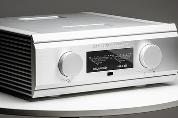
Musical Fidelitylees meer »
NuVista 600.2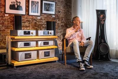
Hifi Studio Wilbertlees meer »
HiVisit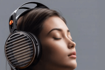
FiiO FT7lees meer »
Review